Interactive Visualizer for Signed-Magnitude Multiplication
What is Signed-Magnitude Multiplication?
This hardware algorithm performs multiplication of signed-magnitude data in digital computers. Unlike traditional shift-and-add methods that shift the multiplicand left, this approach shifts the partial product to the right, offering advantages in hardware design efficiency.
Hardware Architecture
Figure 1: Hardware configuration showing registers and data flow
Key Advantages
Efficient hardware implementation with right-shift operations
Separate sign and magnitude handling
Optimized register usage with combined EAQ register
Predictable execution time based on operand size
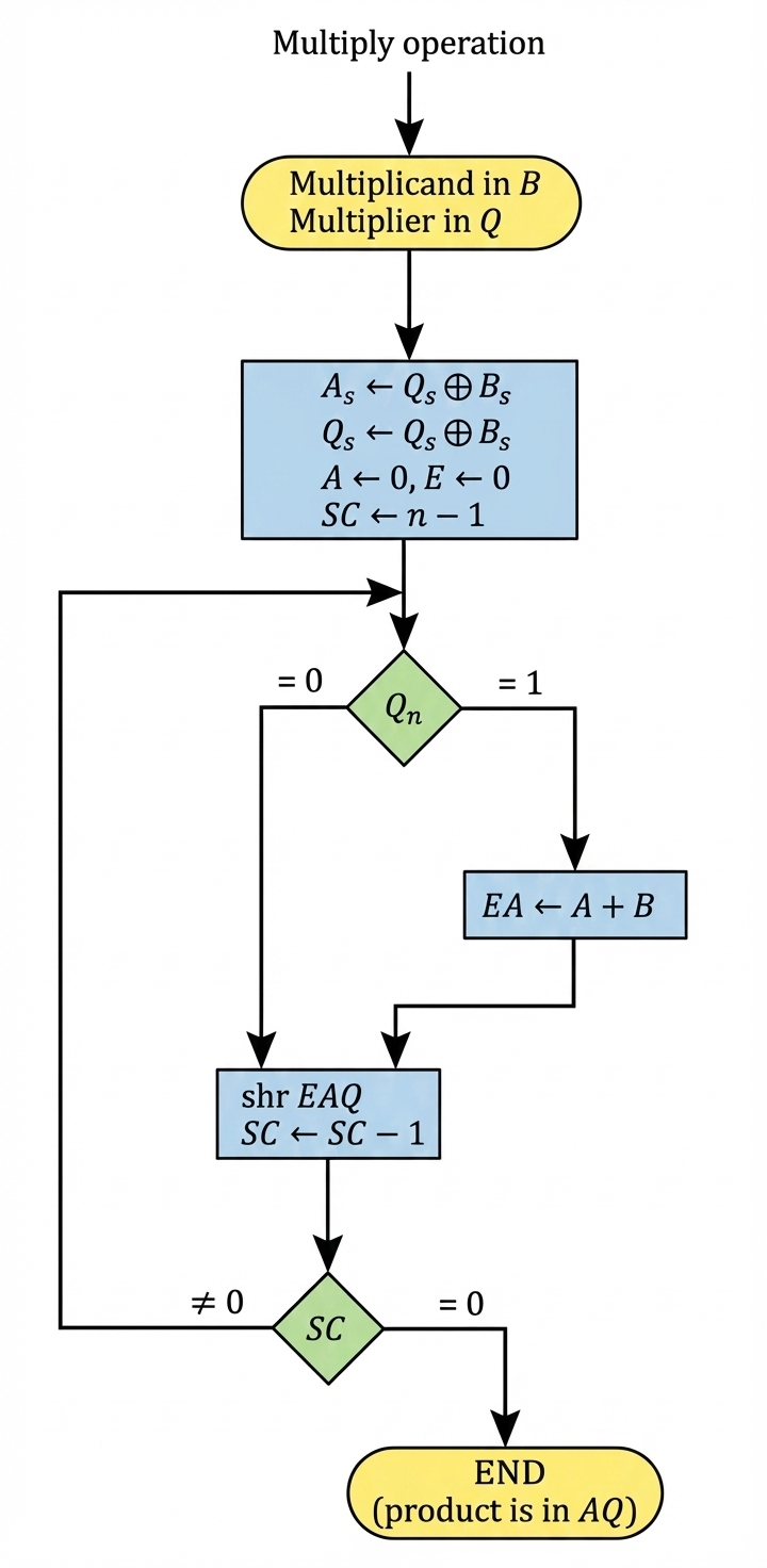
Algorithm Flowchart
Figure 2: Complete flowchart of the hardware multiplication algorithm
Hardware Components
B Register
Multiplicand Holder
Stores the number being multiplied. Remains constant throughout the multiplication process.
Q Register
Multiplier Holder
Initially holds the multiplier. Bits are tested one by one from right to left. Sign bit stored in Qₛ.
A Register
Accumulator
Accumulates the partial product. Initialized to zero and builds the most significant bits of the result.
E Register
1-bit Extension
Holds the carry-out from additions and participates in right-shift operations. Initialized to zero.
SC Counter
Sequence Counter
Tracks iterations. Initialized to n-1 (magnitude bits) and decremented each cycle until reaching zero.
Adder/Complementer
Arithmetic Unit
Performs addition of B to EA when required. Also handles sign bit logic using XOR operation.
Register Configuration
The combined E, A, and Q registers form a (2n+1)-bit register where the final product's magnitude resides. For n-bit operands, the result is a 2n-bit product with a separate sign bit.