Input-Output Configuration
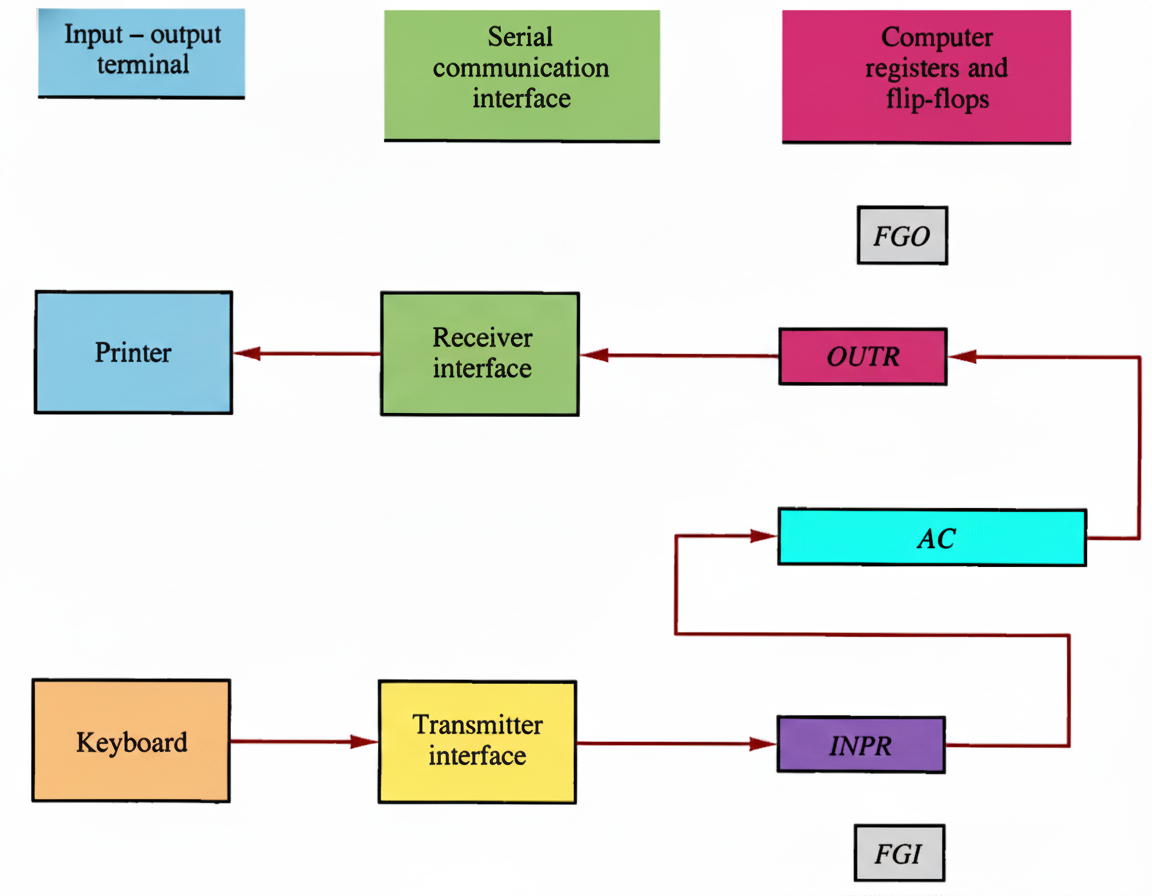
Serial Communication System Architecture
System Architecture
FGI Flag
Input Status Flag
FGO Flag
Output Status Flag
AC Register
Accumulator
📥 Input Register (INPR)
Size: 8 bits
Function: Holds alphanumeric input information from keyboard using ASCII code.
FGI Flag Behavior:
- Set to 1 when new information available
- Cleared to 0 after information is transferred
- Synchronizes timing between input device and computer
📤 Output Register (OUTR)
Size: 8 bits
Function: Stores serial information to be transmitted to printer.
FGO Flag Behavior:
- Set to 1 when output device is ready
- Cleared to 0 when information is transferred
- Indicates when new character can be sent
⚡ Operation Flow
Input Process:
- Key struck → 8-bit code shifted into INPR
- FGI flag set to 1
- Computer checks FGI
- If FGI = 1, transfer INPR to AC
- Clear FGI to 0
Output Process:
- Computer checks FGO
- If FGO = 1, transfer AC to OUTR
- Clear FGO to 0
- Printer prints character
- Set FGO to 1 when complete
I/O Instructions (Opcode: 1111)
Input and output instructions use operation code 1111 and are controlled by bits IR(6-11).
D7IT3 = p (common to all input-output instructions)
IR(i) = Bi [bit in IR(6–11) that specifies the instruction]
| Instruction | Symbol | Hex Code | Action |
|---|---|---|---|
| p : | SC←0 | Clear SC | |
| INP | pB₁₁ : | AC(0-7)←INPR, FGI←0 | Input character to AC |
| OUT | pB₁₀ : | OUTR←AC(0-7), FGO←0 | Output character from AC |
| SKI | pB₉: | If (FGI = 1) then (PC←PC + 1) | Skip on input flag |
| SKO | pB₈: | If (FGO = 1) then (PC←PC + 1) | Skip on output flag |
| ION | pB₇: | IEN←1 | Interrupt enable on |
| IOF | pB₆: | IEN←0 | Interrupt enable off |
Note: The INP instruction transfers input information from INPR into the eight low-order bits of AC. The OUT instruction transfers the eight least significant bits of AC into OUTR. Instructions can be executed in any order or combination by setting bit 6 through 11.
Interactive Demo
Simulate the I/O operation flow:
Ready for simulation...