🔢BCD Adder
Interactive Binary-Coded Decimal Addition
📚What is a BCD Adder?
A Binary-Coded Decimal (BCD) Adder is a specialized digital circuit that performs arithmetic addition on decimal digits represented in 4-bit binary form. Unlike standard binary addition, BCD addition requires special correction logic to maintain valid decimal representation.
In BCD, each decimal digit (0-9) is represented using 4 bits. However, standard binary addition can produce results greater than 9, which are invalid in BCD. The BCD adder automatically detects and corrects these invalid results.
🎮Interactive BCD Addition Demo
⚙️BCD Adder Architecture
A BCD adder stage consists of two main components working together:
Input Signals (9 total):
- A (4 bits): First BCD digit
- B (4 bits): Second BCD digit
- Cin (1 bit): Carry from previous stage
Output Signals (5 total):
- S (4 bits): BCD sum digit
- Cout (1 bit): Carry to next stage
🔧Correction Logic
Correction is required when the binary sum exceeds 9 or generates a carry. In these cases, 0110 (decimal 6) is added to the intermediate sum.
Correction Equation
Where C is the carry-out signal that triggers correction
TABLE 10-4: Derivation of BCD Adder
| Binary Sum | BCD Sum | Decimal | ||||||||
|---|---|---|---|---|---|---|---|---|---|---|
| K | Z8 | Z4 | Z2 | Z1 | C | S8 | S4 | S2 | S1 | |
| 0 | 0 | 0 | 0 | 0 | 0 | 0 | 0 | 0 | 0 | 0 |
| 0 | 0 | 0 | 0 | 1 | 0 | 0 | 0 | 0 | 1 | 1 |
| 0 | 0 | 0 | 1 | 0 | 0 | 0 | 0 | 1 | 0 | 2 |
| 0 | 0 | 0 | 1 | 1 | 0 | 0 | 0 | 1 | 1 | 3 |
| 0 | 0 | 1 | 0 | 0 | 0 | 0 | 1 | 0 | 0 | 4 |
| 0 | 0 | 1 | 0 | 1 | 0 | 0 | 1 | 0 | 1 | 5 |
| 0 | 0 | 1 | 1 | 0 | 0 | 0 | 1 | 1 | 0 | 6 |
| 0 | 0 | 1 | 1 | 1 | 0 | 0 | 1 | 1 | 1 | 7 |
| 0 | 1 | 0 | 0 | 0 | 0 | 1 | 0 | 0 | 0 | 8 |
| 0 | 1 | 0 | 0 | 1 | 0 | 1 | 0 | 0 | 1 | 9 |
| 0 | 1 | 0 | 1 | 0 | 1 | 0 | 0 | 0 | 0 | 10 |
| 0 | 1 | 0 | 1 | 1 | 1 | 0 | 0 | 0 | 1 | 11 |
| 0 | 1 | 1 | 0 | 0 | 1 | 0 | 0 | 1 | 0 | 12 |
| 0 | 1 | 1 | 0 | 1 | 1 | 0 | 0 | 1 | 1 | 13 |
| 0 | 1 | 1 | 1 | 0 | 1 | 0 | 1 | 0 | 0 | 14 |
| 0 | 1 | 1 | 1 | 1 | 1 | 0 | 1 | 0 | 1 | 15 |
| 1 | 0 | 0 | 0 | 0 | 1 | 0 | 1 | 1 | 0 | 16 |
| 1 | 0 | 0 | 0 | 1 | 1 | 0 | 1 | 1 | 1 | 17 |
| 1 | 0 | 0 | 1 | 0 | 1 | 1 | 0 | 0 | 0 | 18 |
| 1 | 0 | 0 | 1 | 1 | 1 | 1 | 0 | 0 | 1 | 19 |
Legend: Green = No correction (0-9) Orange = Correction needed (10-15) Red = Carry generated (16-19)
📐Block Diagram: BCD Adder Circuit
The following diagram shows the internal architecture of a BCD adder with correction logic:
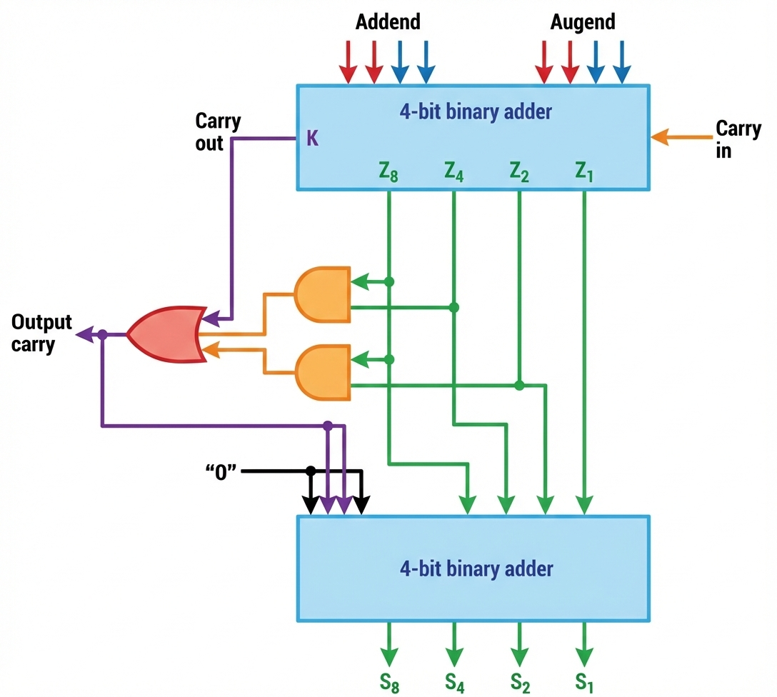
Block diagram showing the two-stage BCD adder with correction logic.
The first 4-bit adder produces intermediate sum (Z), correction logic detects invalid BCD,
and the second adder applies correction (adds 0110) when necessary.