⚡ Priority Interrupt System
Understanding CPU Interrupt Handling Mechanisms
🎯 Overview
A Priority Interrupt System is a mechanism that determines which I/O device receives CPU service when multiple devices request attention simultaneously. This ensures critical operations are handled first, maintaining system efficiency and responsiveness.
🔑 Key Concept
When multiple I/O devices compete for CPU attention, the priority interrupt structure automatically selects and services the highest-priority device first, ensuring critical operations aren't delayed by less important tasks.
📚 Section Structure
| Topic | Key Features | Description |
|---|---|---|
| Daisy-Chaining Priority | Serial priority, simple hardware, fixed priority, propagation delay | Serial priority structure based on physical device position |
| Parallel Priority Interrupt | Fast response, simultaneous checking, complex hardware, no delay | Register-based priority checking for faster access |
| Priority Encoder | Binary output, multiple inputs, resolves priority, combinational circuit | Circuit that converts priority inputs to binary code |
| Interrupt Cycle | CPU halts current task, saves state, executes ISR, resumes execution | Special execution phase for handling interrupts |
| Software Routines | ISR execution, flexible control, programmable, context switching | Software handling of interrupt service |
| Initial and Final Operations | Save registers, disable interrupts, restore state, enable interrupts | Setup and restoration procedures |
🔧 Hardware Priority Techniques
1️⃣ Daisy-Chaining Priority
Concept: Devices are connected in a serial chain where priority is determined by physical proximity to the processor.
Advantage: Simple hardware implementation
Disadvantage: Device closest to CPU always has highest priority
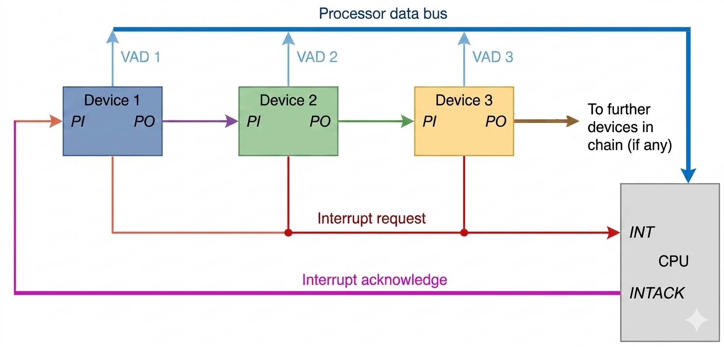
- Request: A device sends an interrupt request on a common line shared by all devices, lowering its signal to notify the CPU.
- Acknowledge: The CPU responds with an interrupt acknowledge signal that goes first to the highest-priority device at the beginning of the chain.
- Check Priority: If that device is not making a request, it passes the acknowledge signal to the next device. If it is requesting an interrupt, it stops the signal from going further by setting its priority output to 0
- Identify and Service: The device that receives the acknowledge (a 1 at its input) but has also made a request knows it is the highest-priority device needing service. It blocks the signal and puts its interrupt vector address (VAD) on the data bus, allowing the CPU to begin the correct interrupt service routine.
2️⃣ Parallel Priority Interrupt
Concept: Uses a register whose status bits are constantly monitored to determine which interrupt to service.
Advantage: Faster access and more flexible priority assignment
Advantage: Can dynamically change priorities
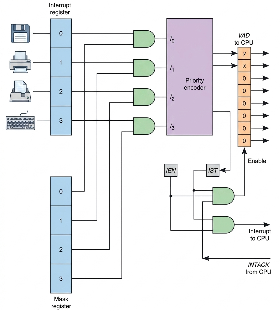
- Interrupt Masking: The Interrupt Register captures requests from devices like disks or printers, which are then passed through AND gates along with the Mask Register to enable or disable specific sources.
- Priority Encoding: The Priority Encoder receives these signals and identifies the highest-priority request (e.g., the Disk is highest priority) while ignoring lower ones.
- CPU Signaling: If an unmasked interrupt exists, the IST (Interrupt Status) and IEN (Interrupt Enable) flip-flops activate a common signal to the CPU.
- Vector Address Generation: Upon receiving an INTACK (Acknowledge) signal from the CPU, the system enables the Vector Address (VAD) to be placed on the data bus, directing the CPU to the correct service routine.
3️⃣ Priority Encoder
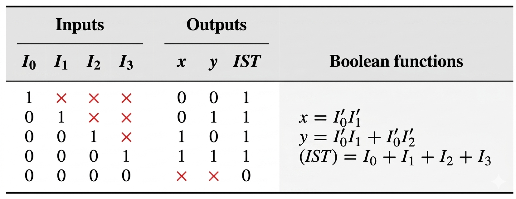
Function: A specialized combinatorial circuit that converts multiple input lines into an n-bit binary code representing the highest priority active input.
Output Code: n-bit binary number
Output represents: Highest priority active input
Example: An 4-to-2 priority encoder takes 4 input lines and produces a 2-bit code (00 to 11) indicating which input has the highest priority.
Comparison
| Feature | Daisy-Chain | Parallel |
|---|---|---|
| Speed | Slower (serial propagation) | Faster (simultaneous checking) |
| Flexibility | Fixed by hardware position | Programmable priorities |
| Complexity | Simple | More complex |
| Cost | Lower | Higher |
🔄 Interrupt Cycle
Based on the provided text, the interrupt cycle is triggered only when both the Interrupt Enable (IEN) flip-flop and the Interrupt Signal (IST) are set to 1.The CPU executes the following steps to pause the current program and switch to the interrupt service routine:
Interrupt Processing Steps
The Stack Pointer (SP) is decremented, and the current Program Counter (PC) value is pushed onto the stack.
The INTACK signal is enabled to notify the hardware that the interrupt is being processed.
he interrupt vector address (VAD) is loaded into the PC to point to the new instruction sequence.
The IEN flip-flop is cleared (0) to prevent further interrupts during the start of the service routine.
The CPU enters the next fetch phase to execute the instruction at the new address.
Microoperations
Here are the specific micro-operations performed during the interrupt cycle, in order:
M[SP] ← PC
INTACK ← 1
PC ← VAD
IEN ← 0
Goto next instruction
💻 Software Handling
Software Routine Tasks
After hardware directs the CPU to the correct service routine, software must handle the actual interrupt processing:
1. The Vector Jump Table
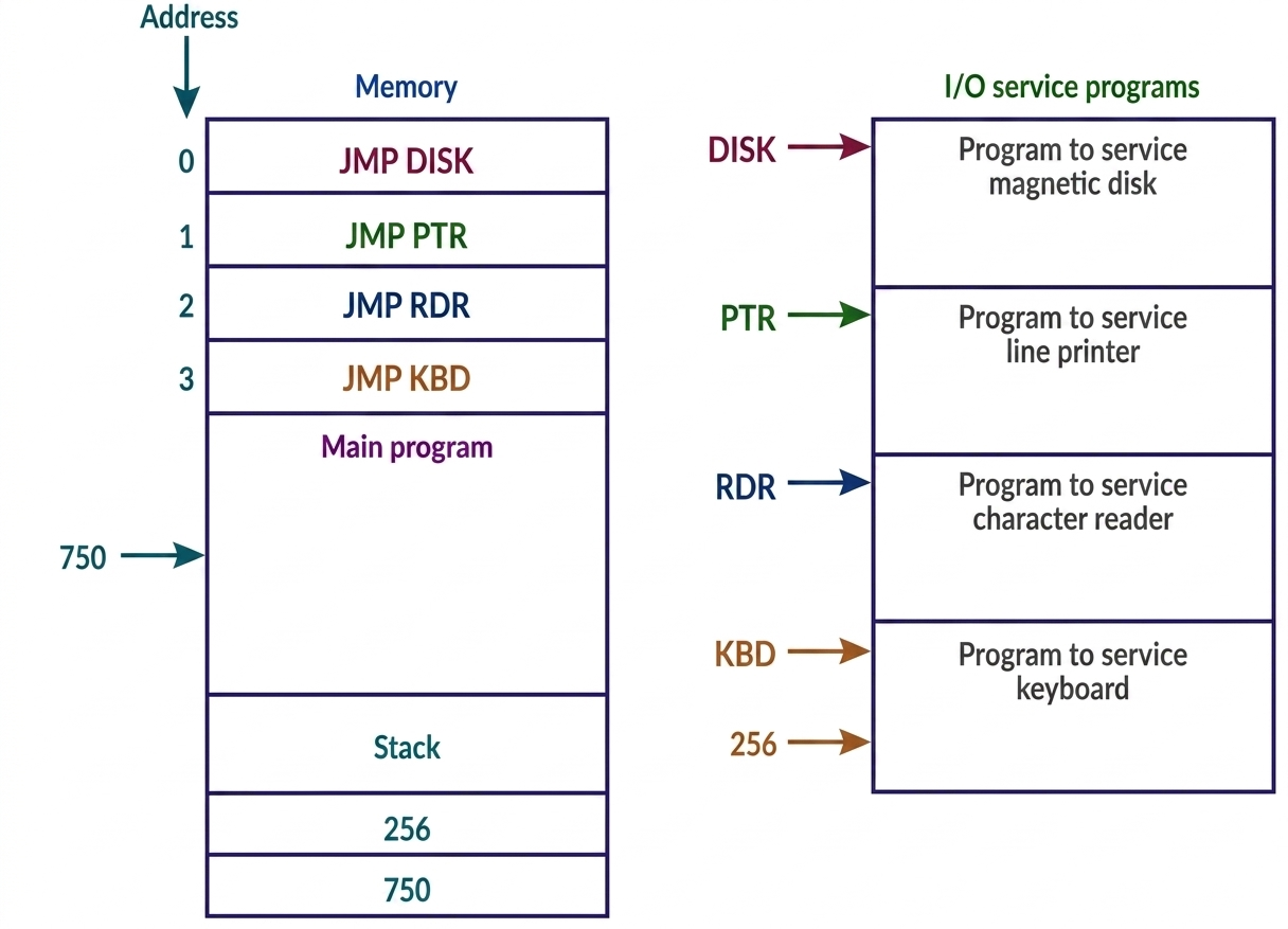
The memory locations 0-3 act as a "jump table." Each location is assigned to a specific hardware device. When an interrupt occurs, the hardware provides the vector address, and the CPU executes the instruction found there. It redirect the CPU from the fixed vector address to the actual memory location of the service program.
1: JMP PTR (Jump to Printer Service Routine)
2: JMP RDR (Jump to Reader Service Routine)
3: JMP KBD (Jump to Keyboard Service Routine) ...
2. The Interrupt Cycle (Hardware/Software Interface)
Before a software routine begins, the hardware initiates an "Interrupt Cycle." While this is hardware-driven, the software must be designed to accommodate the resulting state of the Stack and Program Counter (PC).
M[SP] ← PC ; Store return address
PC ← VAD ; Load Vector address from bus
3. Interrupt Service Routine (ISR) Tasks
Each service program (DISK, KBD, etc.) follows a specific logic flow to ensure data is processed and the CPU can safely return to previous tasks.
- Context Saving (Prologue): If the ISR uses CPU registers (like an Accumulator), the software must save their current values so the main program isn't corrupted.
PUSH AC ; Save Accumulator to Stack
PUSH STATUS ; Save Status Register - Device Servicing: The core logic specific to the hardware device (e.g., reading a character from the keyboard or moving a disk head).
Example (KBD Routine):INP ; Input character from keyboard buffer
STA CHAR_VAR ; Store it in a memory variable - Context Restoration & Return (Epilogue): The routine must restore the registers and perform a "Return from Interrupt" (RETI).
PC ← M[SP]
SP ← SP + 1
4. Handling Nested Interrupts
The text illustrates a scenario where a DISK (high priority) interrupts the KBD (low priority) routine.
Trace of the Stack during Nesting:
- Main Program is at address 749.
- KBD Interrupt occurs: Stack pushes 750. PC moves to KBD routine.
- DISK Interrupt occurs while at KBD address 255: Stack pushes 256. PC moves to DISK routine.
- DISK finishes: Pops 256 into PC. CPU resumes KBD routine.
- KBD finishes: Pops 750 into PC. CPU resumes Main Program.
Initial and Final Operations
📍 Initial Operations (The Prologue)
Disable the mask register bits for the current device and all lower-priority devices. This prevents a less important device from interrupting the current routine.
Reset the status bit so the hardware is ready to latch and recognize a new, higher-priority interrupt request.
Push the contents of the Accumulator (AC), Status Register, and any other working registers onto the stack to prevent data loss.
Explicitly set IEN to 1. Since the hardware clears IEN during the interrupt cycle, this step "re-opens the door" for higher-priority devices to interrupt this ISR.
🏁 Final Operations (The Epilogue)
Disable interrupts temporarily. This ensures that the restoration of registers and the return address (Steps 2–5) happens atomically without being interrupted.
Pop the saved values from the stack back into the processor registers (AC, etc.).
Clear the specific bit in the interrupt register belonging to the source that was just serviced so it doesn't immediately trigger another interrupt.
Re-enable the bits in the mask register for lower-priority devices, allowing them to request interrupts again.
Pop the return address from the stack into the Program Counter (PC) and set IEN to 1 to resume normal operation.
For nesting to work, the software routine must usually re-enable interrupts (Set Interrupt Enable bit) early in its execution, otherwise, the hardware will block all subsequent interrupts until a return is executed.
🎮 Interactive Priority Interrupt Demo
Click on devices to simulate interrupt requests and see how the priority system handles them!
Devices (Click to Request Interrupt)
Highest Priority - Critical disk operations
High Priority - Time-sensitive network packets
Medium Priority - User input
Low Priority - Non-critical output
> IEN = 1 (Interrupts Enabled)
📊 Demo Statistics
Interrupts Processed: 0
Pending Interrupts: 0