Micro-programmed Control Organization
Understanding the Heart of Computer Architecture
🧠Control Memory
Control memory is the heart of micro-programmed control units, storing microinstructions that define the control signals for each machine instruction.
Interactive Control Memory Visualization
Click on memory blocks to see their contents:
Control Memory Structure
Control memory consists of:
- Address Field: Specifies the next microinstruction address
- Control Field: Contains control signals for the datapath
- Condition Field: Determines branching conditions
Memory Organization
Each memory location contains a complete microinstruction with multiple fields for different control functions. The width typically ranges from 50-100 bits to accommodate all necessary control signals.
Access Pattern
Sequential access is the default, but branch microinstructions can alter the sequence based on condition codes or instruction opcodes.
🏗️Design of Control Unit
The control unit design involves careful consideration of microinstruction format, sequencing logic, and control signal generation.
Control Unit Architecture
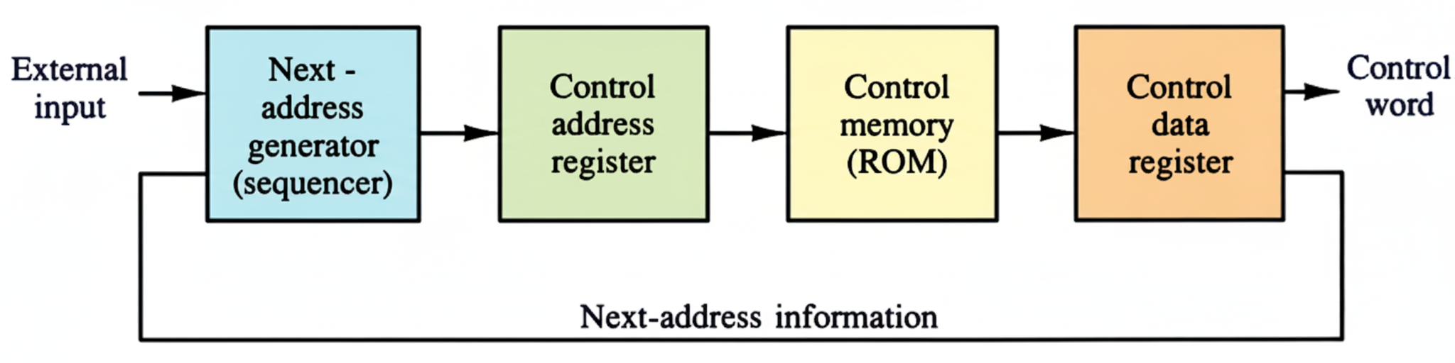
Control Memory Components:
📍Control Address Register (CAR)
Also referred to as the Next Address Register, the Control Address Register (CAR) holds the address of the microinstruction to be read from the control memory (ROM).
- It specifies the address of the microinstruction to be read.
- The next address is either the next sequential address or an address generated based on external input conditions.
📜Control Data Register (CDR)
The Control Data Register (CDR) holds the present microinstruction while its microoperations are being executed and the next address is computed.
- The microinstruction in the CDR contains the control word that specifies one or more microoperations for the data processor.
- It also contains the bits that determine the address sequence for the control memory.
➡️Program Sequencer (Next Address Generator)
The Next Address Generator, often called the Program Sequencer or Microprogram Sequencer, determines the address sequence that is read from the control memory.
Typical functions:
- Incrementing the CAR to select the next sequential microinstruction.
- Loading an address from the control memory into the CAR (e.g., for branching).
- Transferring an external address to the CAR (e.g., to start control operations).
⚙️Microinstruction Execution Cycle
The execution of a machine instruction involves a series of sequential microinstructions in control memory. In a simplified view:
- The CAR is loaded with the address of the first microinstruction for the operation.
- The microinstruction is read from Control Memory and loaded into the CDR.
- The control word bits in the CDR initiate the specified microoperations in the data processor.
- The address sequencing bits in the CDR are used by the Program Sequencer to determine the address of the next microinstruction (which is then loaded into the CAR).
- The cycle repeats until the machine instruction is complete, and control returns to the fetch phase for the next instruction.
⚖️Hardwired vs Microprogrammed Control
Understanding the key differences between hardwired and microprogrammed control units.
| Aspect | Hardwired Control | Microprogrammed Control |
|---|---|---|
| Speed | Faster execution | Slower due to memory access |
| Flexibility | Fixed, difficult to modify | Highly flexible and modifiable |
| Complexity | Complex hardware design | Simpler hardware, complex software |
| Cost | Higher hardware cost | Lower hardware cost |
| Debugging | Difficult to debug | Easier to debug and test |
| Instruction Set | Limited instruction set | Can support complex instruction sets |
| Development Time | Longer development time | Shorter development time |
| Applications | RISC processors, simple CPUs | CISC processors, complex systems |