🔬 Microprogramming Example
Explore the fascinating world of microprogram control units with interactive examples and beautiful visualizations
🏗️ Computer Hardware Configuration
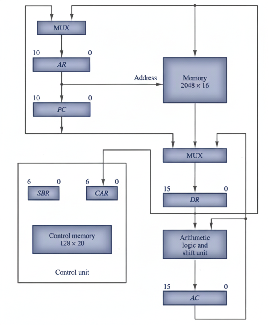
A microprogrammed control unit uses control memory to store microprograms, which are sequences of microinstructions. Let's explore the key hardware components:
📋 Microinstruction Format
Each microinstruction is a 20-bit control word that initiates microoperations and determines the next microinstruction address:
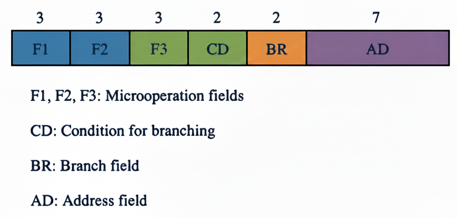
F1, F2, F3
Three 3-bit fields specifying microoperations (9 bits total, 21 distinct operations)
CD Field
2-bit condition field: U(00), I(01), S(10), Z(11)
BR Field
2-bit branch field: JMP(00), CALL(01), RET(10), MAP(11)
AD Field
7-bit address field for jump and call operations
🔗 Microinstruction Structure
Each line of the assembly language microprogram defines a symbolic microinstruction. Each symbolic microinstruction is divided into five fields:
1 Label Field
The label field may be empty or it may specify a symbolic address. A label is terminated with a colon (:).
2 Microoperations Field
This field consists of one, two, or three symbols, separated by commas, from those defined above in F1, F2, F3 . There may be no more than one symbol from each F field. The NOP symbol is used when the microinstruction has no microoperations. This will be translated by the assembler to nine zeros.
3 CD Field
The CD field has one of the letters U, I, S, or Z.
4 BR Field
The BR field contains one of the four symbols JMP, CALL, RET, or MAP .
5 AD Field
The AD field specifies a value for the address field of the microinstruction in one of three possible ways:
- With a symbolic address, which must also appear as a label.
- With the symbol NEXT to designate the next address in sequence.
- When the BR field contains a RET or MAP symbol, the AD field is left empty and is converted to seven zeros by the assembler.
🔄 Microinstruction Fetch Routine
The fetch routine retrieves the next computer instruction from main memory:
| Step | Operation | Description |
|---|---|---|
| 1 | AR ← PC | Load program counter value into address register |
| 2 | DR ← M[AR], PC ← PC + 1 | Read instruction from memory and increment PC |
| 3 | AR ← DR(0-10), CAR(2-5) ← DR(11-14), CAR(0,1,6) ← 0 | Extract address and map opcode to microprogram start |
FETCH: PCTAR U JMP NEXT ; AR ← PC
READ, INCPC U JMP NEXT ; DR ← M[AR], PC ← PC + 1
DRTAR U MAP ; AR ← DR(0-10), map opcode
🔗 Indirect Addressing Subroutine
The INDRCT subroutine handles indirect addressing for memory reference instructions:
INDRCT:READ U JMP NEXT ; DR ← M[AR]
DRTAR U RET ; AR ← DR, SBR ← CAR
🎯 Interactive Instruction Examples
Explore microprograms for common computer instructions:
Select an instruction to see its microprogram!
Click any button above to explore how different instructions are implemented using microprograms.