🖥️ Microprocessor Control Unit

Interactive Guide to Address Selection & Instruction Mapping

1
Control Unit Architecture
1
Instruction code enters the system
2
Mapping logic processes the instruction
3
Multiplexers route control signals
4
Control memory outputs microoperations

Instruction Code

High-level machine instruction input

The starting point where machine instructions enter the control unit for processing

Mapping Logic

Converts instruction opcodes to addresses

Critical component that translates instruction opcodes into control memory addresses

Multiplexers

Route control signals based on conditions

Switch between different address sources based on branch logic and status bits

Control Address Register (CAR)

Holds current control memory address

Stores the address of the current microinstruction being executed

Control Memory

Stores microinstructions for execution

ROM or RAM containing microinstructions that control processor operations

Subroutine Register (SBR)

Saves return addresses for subroutines

Stack-like structure for managing microprogram subroutine calls

📊 Original Control Unit Architecture Diagram
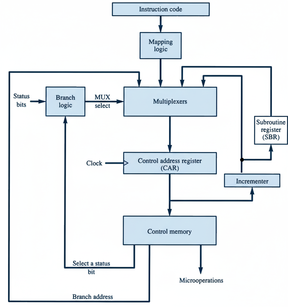
Control Memory
This diagram shows how the control unit selects addresses for control memory through mapping logic, multiplexers, and various control signals.
2
Instruction to Microinstruction Mapping
Computer Instruction:
1
0
1
1
address
■ Opcode    ■ Address Field
⬇️
Mapping Bits:
0
×
×
×
×
0
0
■ Mapping Logic Output    ■ Don't Care Bits
⬇️
Microinstruction Address:
0
1
0
1
1
0
0
■ Final Control Memory Address

🔄 Original Instruction Mapping Diagram

Mapping from instruction code to microinstruction address Computer instruction: Opcode 1 0 1 1 address Mapping bits: 0 × × × × 0 0 Microinstruction address: 0 1 0 1 1 0 0
This diagram illustrates the step-by-step mapping process from a machine instruction's opcode to the final microinstruction address in control memory.
🎯 Key Insight

The opcode bits (1011) are directly mapped to create the microinstruction address, with additional padding bits (0 and 00) to form the complete 7-bit address.

⚡ Flexibility

Don't care bits (x) in the mapping scheme dedicate a block of control memory addresses to an instruction's microprogram, allowing for future expansion of its microinstruction routine without altering the overall addressing structure.

3
Key Features & Benefits
⚡

Fast Execution

Direct mapping reduces instruction decode time

🔄

Flexible Control

Multiplexers enable conditional branching

🎯

Precise Addressing

Status bits provide fine-grained control

🧠

Smart Memory

Subroutine register enables modular design

Start Learning Address Sequencing