📊 Input-Output Interface

Input-Output Organization

🎯 Context and Purpose

The Input-Output Interface is central to understanding how processors interact with external peripherals. The physical organization includes an Input-Output Processor (IOP) containing electronic circuits for controlling information transfer between the computer and the outside world.

1
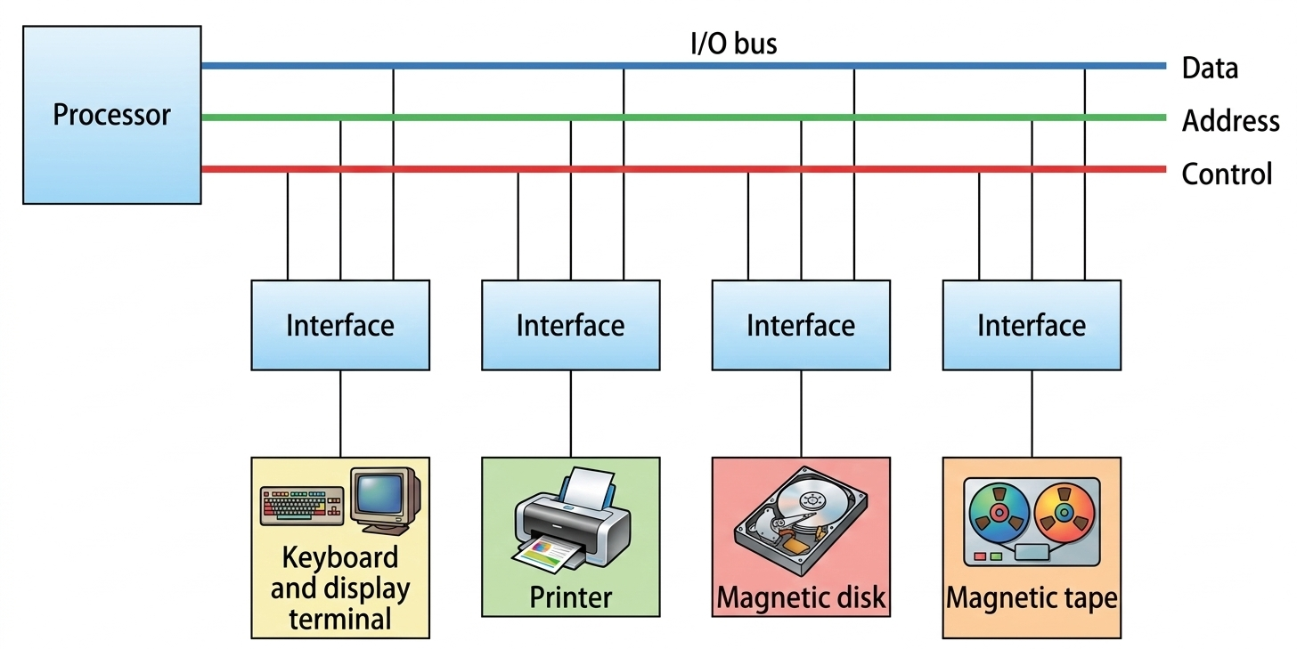
I/O Bus and Interface Modules
▼

This architecture defines how various I/O devices connect to the core computer system.
BCD Multiplication Register

🔌 Key Component

  • Address Decoder: Enables the interface to recognize when the processor is specifically addressing it.
  • Buffer Register: A temporary storage area that holds data being moved between the high-speed bus and the (usually) slower peripheral.
  • Status Register: A register used to store "bits" that represent the current state of the device, which the processor monitors to decide when to send or receive data.

🔌 Key Command

  • I/O Command: function code sent by the processor to an interface that instructs the interface and its connected peripheral device to perform a specific operation, where the meaning of the command depends on the particular peripheral being addressed.
  • Control Command: Used to activate a peripheral and give it specific operational instructions (e.g., "rewind" or "start moving")
  • Status Command: Used to check the condition of the peripheral or interface by reading bits in a status register to determine readiness or detect errors such as a busy device or transfer failure.
  • Data Output Command: Triggers the interface to take data from the bus and place it into its internal buffer register, eventually sending it to the peripheral.
  • Data Input Command: Interface receives data from the peripheral, places it in the buffer register, and then puts it onto the data lines for the processor to read.
CPU Communication Device Management Data Transfer
2
I/O versus Memory Bus
▼

This topic distinguishes between bus structures for accessing peripheral interfaces versus main memory.

⚡Method 1: Independent Buses (I/O Processor Architecture)

  • Dual Pathway: Utilizes two entirely separate sets of data, address, and control buses—one dedicated to Memory and the other to I/O.
  • Specialized Hardware: Features a dedicated I/O Processor (IOP), also known as a data channel, in addition to the CPU.)
  • Parallelism: The IOP acts as an independent pathway, managing information transfer between external devices and internal memory without constantly involving the CPU.
  • Communication Flow: The memory unit communicates with both the CPU and the IOP via the memory bus, while the IOP handles devices via the separate I/O bus.

⚡Method 2: Common Bus with Separate Control Lines (Isolated I/O)

  • Shared Wiring: The physical data and address lines are shared between Memory and I/O components.
  • Distinct Commands: Even though the "road" (bus) is the same, the system uses separate control lines for each. This means there are specific signals to distinguish between a "Memory Read/Write" and an "I/O Read/Write."

⚡Method 3: Common Bus with Common Control Lines (Memory-Mapped I/O)

  • Unified Architecture: Both Memory and I/O share the same data, address, and control lines.
  • Address Space Integration: In this setup, the CPU does not distinguish between a memory address and an I/O device address. They are treated as part of the same physical map, using the same set of read/write commands.
3
Isolated versus Memory-Mapped I/O
▼

Two primary methods for managing control and data signals for I/O modules:

🗺️ Comparison

Isolated I/O
🚦I/O and Memory have separate address spaces.
🚦Uses separate control lines (e.g., I/O Read/Write vs. Memory Read/Write).
🚦 Requires distinct INPUT and OUTPUT instructions.
🚦 The full memory address range remains available for RAM.
🚦 Limited to specific I/O-only instructions to manipulate I/O data.
🚦 The bus tells components if an address is for I/O or Memory via control lines.
Memory-Mapped I/O
📍I/O and Memory share a single, common address space.
📍Uses the same set of Read/Write signals for both I/O amd Memory.
📍Uses standard memory-reference instructions (e.g., LOAD, STORE).
📍I/O registers occupy memory addresses, reducing the range available for RAM.
📍Can use any memory-referencing instruction to manipulate I/O data.
📍The system treats an I/O interface register as if it were just another memory word.
4
Example of I/O Interface
▼

A practical implementation using the basic computer architecture from Unit 3:

INPR
Input Register - Holds 8-bit character received from input device
OUTR
Output Register - Holds 8-bit character for output device

🚩 Flag Flip-Flops

FGI (Input Flag)
Set to 1: New input character available
Cleared to 0: Character accepted by computer
Synchronizes fast CPU with slower input device
FGO (Output Flag)
Set to 1: OUTR ready for new character
Cleared to 0: Character accepted by output device
Controls output synchronization

🔄 Data Transfer Mechanism

The interface allows serial data transfer between external terminals (keyboard/printer) and parallel internal registers (INPR/OUTR). This demonstrates the basic functional requirements of an I/O interface for data transfer and synchronization.

Start Learning I/O Interface Unit