The Instruction Cycle
Interactive Learning Experience - Computer Architecture Fundamentals
Instruction Cycle Visualization
The fundamental phase where the computer retrieves and interprets the next instruction from memory.
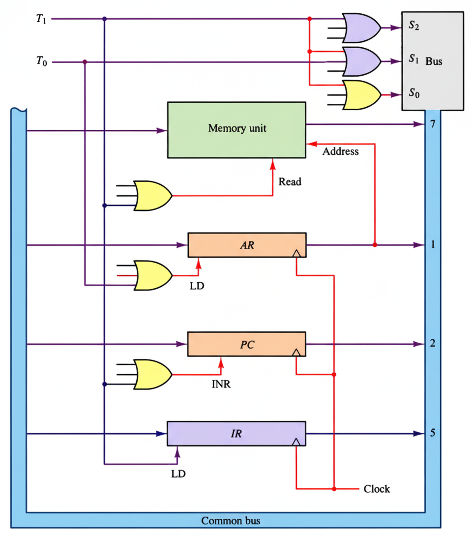
- AR ← PC: Transfer Program Counter to Address Register
- IR ← M[AR]: Load instruction from memory to Instruction Register
- PC ← PC + 1: Increment Program Counter for next instruction
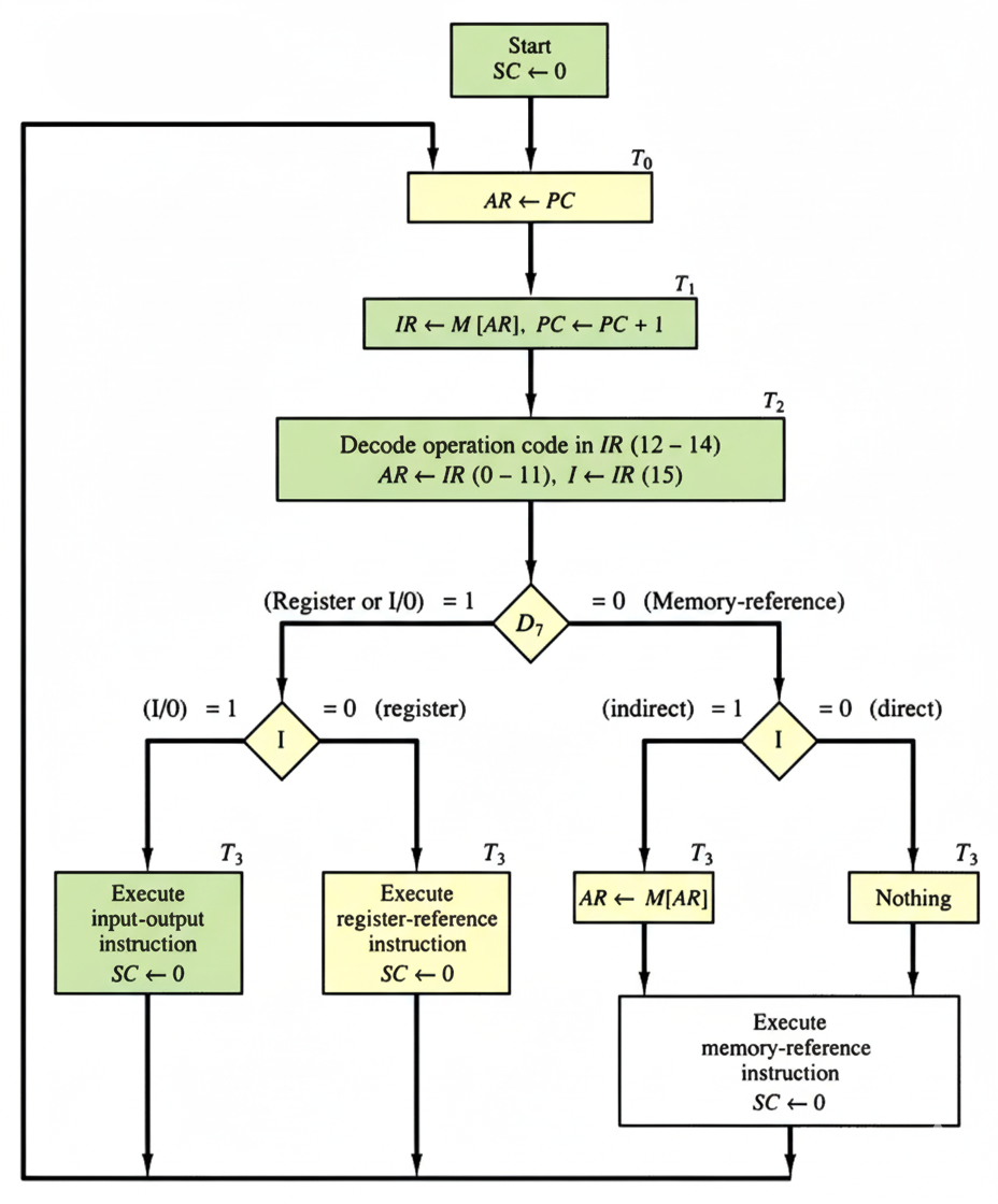
- D0-D7 ← Decode IR(12-14): Decode operation code
- AR ← IR(0-11): Transfer address part to Address Register
- I ← IR(15): Set addressing mode bit
Based on the decoded instruction, determine the execution path and handle addressing modes.
Memory-Reference (D7 = 0)
Instructions that require operands from memory. Includes AND, ADD, LDA, STA, BUN, BSA, ISZ.
Indirect (I=1): Fetch effective address, then execute at T4
Register-Reference (D7 = 1, I = 0)
Operations on processor registers. Examples: CLA, INC, HLT.
Input-Output (D7 = 1, I = 1)
Data transfer between processor and I/O devices. Examples: INP, OUT.
For indirect addressing, calculate the actual memory address of the operand.
- AR ← M[AR]: Fetch effective address from memory
- Only executed when I = 1 (indirect addressing)
- Makes AR point to the actual operand location
Perform the actual operation specified by the instruction using the correct operand address.
- Perform the specific operation (AND, ADD, LOAD, etc.)
- Update processor registers as needed
- Clear Sequence Counter (SC ← 0)
- Return to T0 for next instruction fetch
Key Concepts
Program Counter (PC)
Holds the address of the next instruction to be executed. Automatically incremented after each fetch.
Instruction Register (IR)
Stores the current instruction being executed. Contains opcode and address fields.
Address Register (AR)
Holds memory addresses for instruction fetch and operand access.
Sequence Counter (SC)
Controls timing signals (T0, T1, T2...) that orchestrate the instruction cycle phases.
Direct vs Indirect
Direct addressing uses the address directly; indirect requires an additional memory access to get the actual address.
Timing Signals
T0, T1, T2, T3, T4... control the sequence of microoperations within each instruction cycle.