🖥️ Common Bus System
Interactive Computer Architecture Learning Module
💡Why a Common Bus?
A basic computer system has eight registers, memory, and a control unit. Instead of connecting every register to every other register (which would require excessive wiring), we use a common bus system.
Key Benefit: Efficient information transfer between multiple registers with minimal hardware complexity!
- Reduces wiring complexity exponentially
- Uses multiplexers or three-state buffers
- Enables simultaneous access control
- Scalable for multiple components
📐System Specifications
16-bit Common Bus
7 Connected Components
3 Selection Inputs
Components Connected:
- 6 Registers (AR, PC, DR, AC, IR, TR)
- 1 Memory Unit (4096×16 bits)
- Control via S₂S₁S₀ selection lines
Memory Configuration: 4096 words × 16 bits per word
📐System Architecture
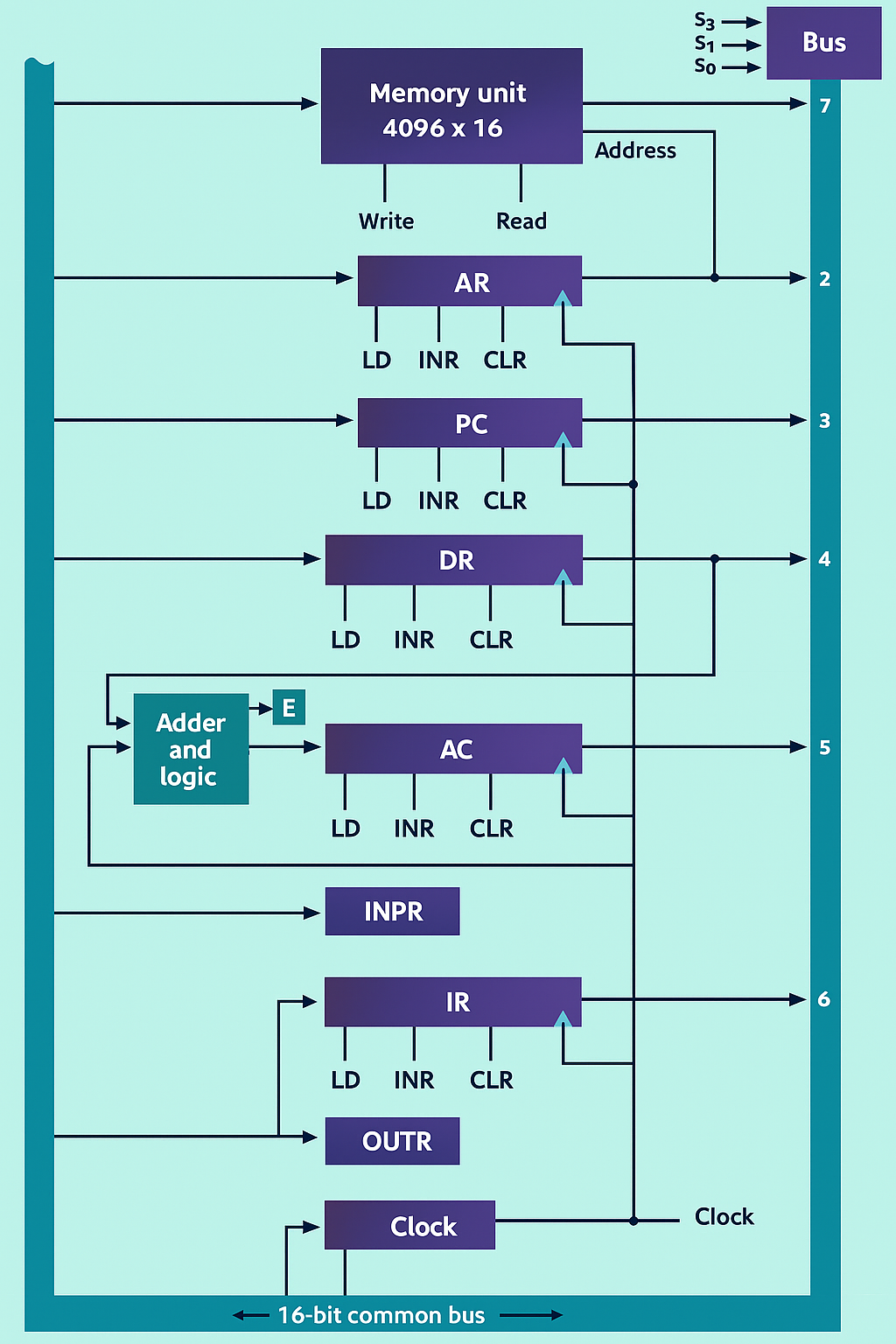
🎮Interactive Bus Simulator
Click a register to select it on the bus
AR
Address Register (12-bit)
PC
Program Counter (12-bit)
DR
Data Register (16-bit)
AC
Accumulator (16-bit)
IR
Instruction Register (16-bit)
TR
Temporary Register (16-bit)
Memory
Memory Unit (16-bit)
16-BIT COMMON BUS
Bus Selection Control: S₂S₁S₀
S₂
0
S₁
0
S₀
0
Select a register or toggle selection bits
📊Bus Selection Table
| Output Line | Register/Unit | Binary Select (S₂S₁S₀) | Description |
|---|---|---|---|
| 1 | AR | 001 | Address Register (12-bit, 4 MSBs = 0) |
| 2 | PC | 010 | Program Counter (12-bit, 4 MSBs = 0) |
| 3 | DR | 011 | Data Register (16-bit) |
| 4 | AC | 100 | Accumulator (16-bit, via Adder/Logic) |
| 5 | IR | 101 | Instruction Register (16-bit) |
| 6 | TR | 110 | Temporary Register (16-bit) |
| 7 | Memory | 111 | Memory Unit (16-bit output) |
| — | None | 000 | No register selected |
🔧Register Details
16-bit Registers
- DR, TR: Full 16-bit data transfer
- AC: Connected via Adder/Logic Circuit
- IR: Holds instruction code (LD only)
12-bit Registers
- AR, PC: Memory address registers
- 4 MSBs set to 0 on bus transfer
- Only 12 LSBs loaded from bus
- PC supports INR (increment)
8-bit I/O Registers
- INPR: Connected to Adder/Logic Unit
- OUTR: Receives from bus only
⚙️Control Inputs
Most registers have three control inputs:
LD - Load
INR - Increment
CLR - Clear
Special Cases:
- IR: Only has LD input
- AC: Loads via Adder/Logic Circuit
- Memory: Uses Read/Write signals
- AR: Always specifies memory address
Memory Operations:
Read: DR ← M[AR]
Write: M[AR] ← Data from Bus
Read: DR ← M[AR]
Write: M[AR] ← Data from Bus