📡 Asynchronous Data Transfer

📌

Context & Overview

Asynchronous data transfer is the procedure for handling information transfer between units that operate independently, where data flow is not controlled by a common clock signal.

Why Asynchronous Transfer?

  • Peripheral devices operate much slower than the CPU
  • Different devices have different timing requirements
  • Synchronizes fast CPU clock with variable device timing
  • Enables reliable communication over long distances
1

Strobe Control

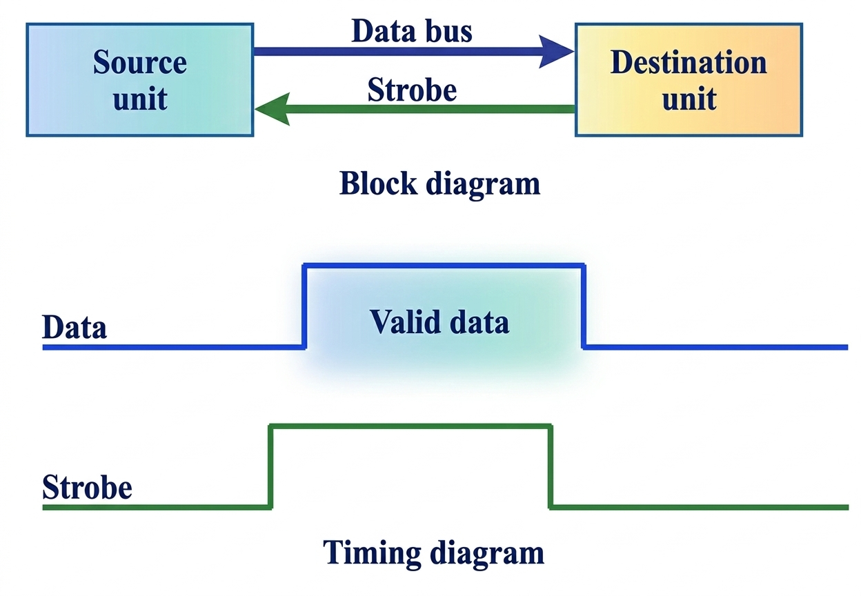
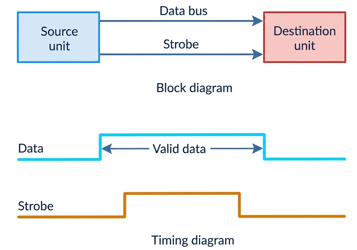
Strobe control is a fundamental method for asynchronous parallel data transfer using a single control line.

Interactive Demo: Strobe Signal

SOURCE
→
STROBE
→
DEST

Key Characteristics:

  • Uses single control line to initiate transfer
  • Can be source-initiated or destination-initiated
  • Simple but no confirmation of successful transfer
  • Unreliable for long-distance communication
Source Initiated Strobe Control
Source Initiate Strobe

In a strobe-controlled data transfer, the source unit first places data on the bus and waits for it to settle before activating the strobe pulse. This signal remains active long enough for the destination unit to receive the information, often using the falling edge of the pulse to trigger the transfer into an internal register. Once the strobe is disabled, the data is considered invalid, and the source may subsequently remove it from the bus. New valid data is only recognized by the system when the strobe signal is enabled once again.

Destination Initiated Strobe Control
Destination Initiate Strobe

Based on the provided text, the data transfer process is initiated by the destination unit activating a strobe pulse to request data from the source. The source unit responds by placing valid binary information on the data bus, where it must remain long enough for the destination to accept it. The falling edge of this strobe pulse can trigger a register in the destination unit, after which the destination disables the strobe. Finally, the source removes the data from the bus once a predetermined time interval has passed.

2

Handshaking

Handshaking is a more robust method using two or three control signals to ensure reliable synchronization.

Interactive Demo: Handshaking Process

SENDER
→
READY
←
ACK
→
RECEIVER

Handshaking Signals:

  • Data Ready Signal: Source informs destination data is available
  • Data Accepted (ACK): Destination confirms receipt of data
  • Provides explicit synchronization timing
  • Ensures both sender and receiver are coordinated
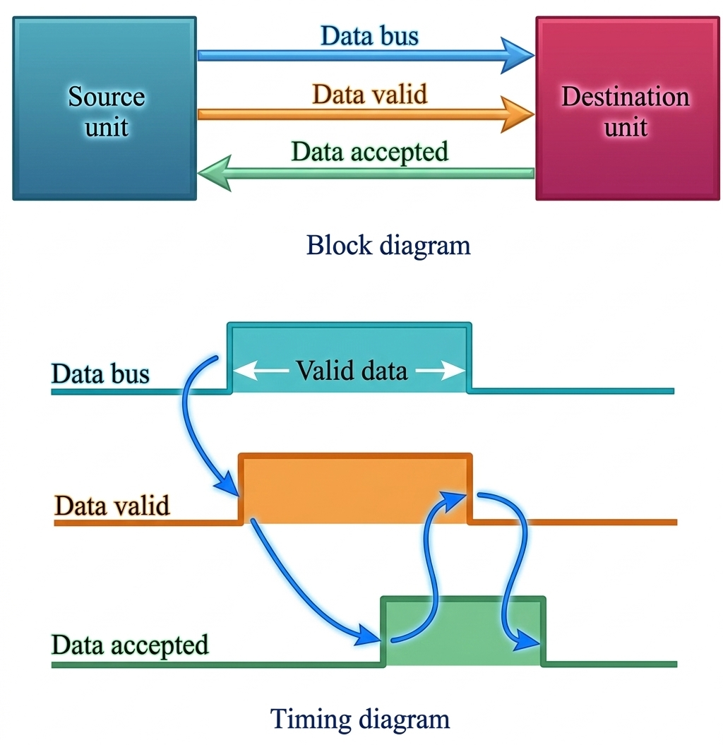
Source Initiated Transfer using Handshaking
Source Handshaking

This process ensures reliable communication through a four-step sequence: the source places data on the bus and enables the data valid signal, the destination activates data accepted once it receives the information, and both signals are then sequentially disabled to return the system to its initial state. This synchronized exchange allows for arbitrary delays between states, ensuring the source never sends new data until the destination is ready.

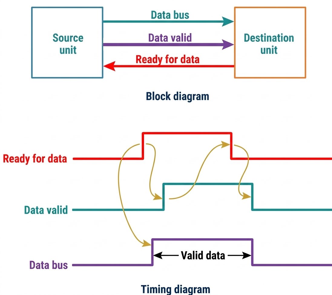
Destination initiated transfer using Handshaking
Source Handshaking

In a destination-initiated transfer, the process begins when the destination unit sends a ready for data signal, prompting the source unit to place data on the bus. This method is functionally identical to a source-initiated transfer, with the primary difference being the initial state of the handshake and the naming of the signals. Essentially, the ready for data signal acts as the logical complement to the data accepted signal used in source-initiated sequences.

Timeouts:

  • Initialization: An internal clock begins counting as soon as a unit enables one of its handshaking control signals.
  • Error Detection: If the corresponding return handshake signal is not received within a predetermined time period, the unit assumes a fault has occurred.
  • Response: The resulting timeout signal triggers an alarm or interrupts the processor to execute a service routine for error recovery.
3

Asynchronous Serial Transfer

Serial transfer transmits information one bit at a time, sequentially - essential for long-distance communication.

Serial Data Frame Structure

START
D0
D1
D2
D3
D4
D5
D6
D7
P
STOP

START bit → 8 Data bits → Parity bit → STOP bit

Serial Transfer Features:

  • More economical than parallel lines for long distances
  • Uses shift registers for parallel-to-serial conversion
  • Start/Stop bits frame data for synchronization
  • Transmitter and receiver use separate clocks
Baud Rate

The baud rate represents the speed of serial data transmission and is equivalent to the total number of bits sent per second, including overhead. In the example provided, each character consists of 11 bits (one start bit, eight information bits, and two stop bits) and is transmitted at a rate of 10 characters per second. Consequently, the resulting transfer rate is 110 baud, where each individual bit has a duration of approximately 9.09 ms.

4

Asynchronous Communication Interface

Dedicated hardware module (UART/USART) managing asynchronous serial communication.

Interface Functions:

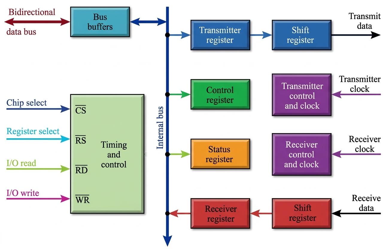
  • Initialization: The CPU starts by sending a "control byte" to the Control Register to set up how the data will be transferred.
  • Transmitting Data: The CPU writes a data byte to the Transmitter Register, which then moves it to a shift register to be sent out bit-by-bit (serially).
  • Receiving Data: Incoming serial data is collected in a shift register; once a full byte is ready, it moves to the Receiver Register for the CPU to read.
  • Monitoring Status: The Status Register acts like a dashboard, using "flags" to tell the CPU if data is ready, if a transmission is finished, or if any errors happened.
  • CPU Controls: The CPU uses the Chip Select (CS) signal to "wake up" the interface and uses the Register Select (RS) along with Read/Write lines to pick which specific register it wants to talk to.
Communication Interface Block Diagram
Source Handshaking

Internal structure showing parallel data registers, serial shift registers, control logic, and clock dividers.

Interface Control Logic
Source Handshaking

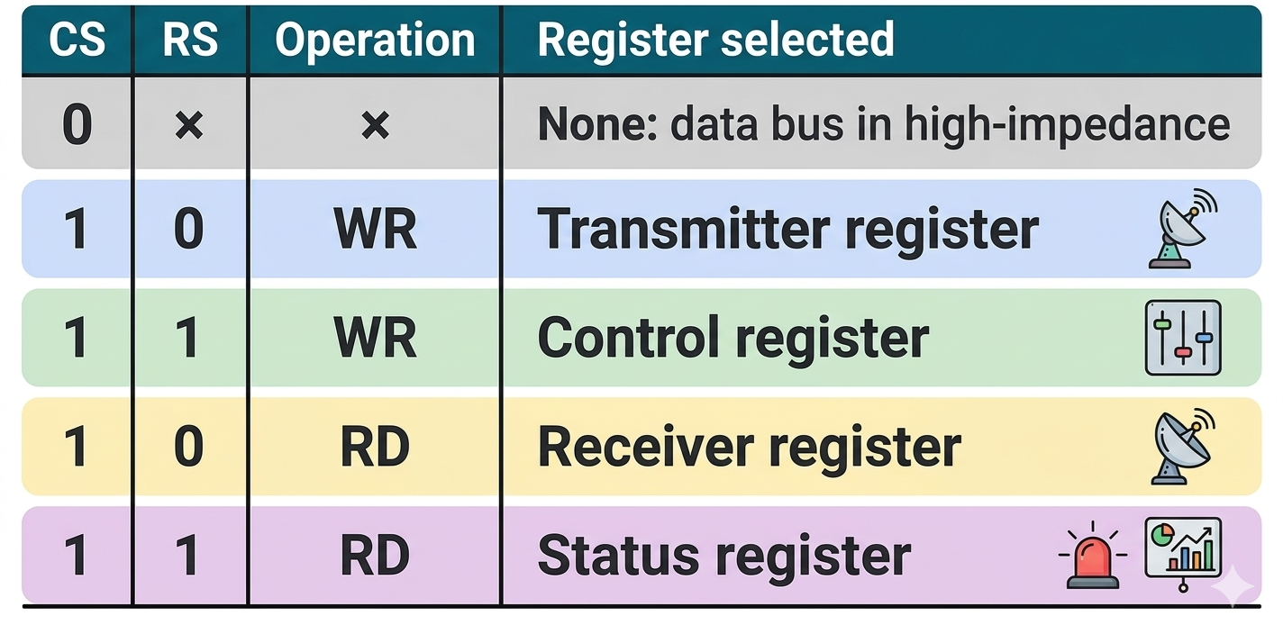
It outlines the logic for register selection in a communication interface, likely a UART or similar I/O device, based on Chip Select (CS) and Register Select (RS) signals. It defines whether the system is performing a Read (RD) or Write (WR) operation to access specific internal components like the Transmitter, Receiver, Control, or Status registers. When the Chip Select is inactive (0), the data bus enters a high-impedance state, effectively disconnecting the device from the bus.

Transmitter:

  • Status Check: The CPU first reads the Status Register to see if the transmitter register is empty and ready for new data.
  • Loading Data: If empty, the CPU sends a character to the Transmitter Register, and the interface automatically marks it as "full" by clearing a flag.
  • Framing the Data: The interface adds a start bit (set to 0) at the beginning and stop bits at the end of the character to prepare it for travel.
  • Shifting Out: The character moves from the transmitter register into a Shift Register, which sends the data out one bit at a time at the set baud rate.
  • Double Buffering: Because the transmitter register becomes "empty" as soon as data moves to the shift register, the CPU can load a second character while the first one is still being sent out.

Receiver:

  • Idle State: When no data is being sent, the receive line stays at a 1-state (high).
  • Detection: The receiver constantly watches for a 0 signal, which acts as the start bit to trigger the receiving process.
  • Collection: Once the start bit is found, incoming bits are "shifted" into a shift register one by one at the specific baud rate.
  • Validation: After the data bits arrive, the interface automatically checks the parity and stop bits to ensure the information is correct.
  • Storage: The cleaned-up character (without start/stop bits) is moved to the receiver register, and a flag is set in the status register to show it is "full."
  • CPU Pickup: The CPU monitors that flag; when it sees the register is full, it reads the data from the receiver register.
5

First-In, First-Out (FIFO) Buffer

Temporary storage managing rate differences between asynchronous units.

Interactive FIFO Demo

Push adds data, Pop removes (First-In, First-Out)

FIFO Characteristics:

  • Prevents data loss when sender is faster than receiver
  • Data read in same order as written (FIFO principle)
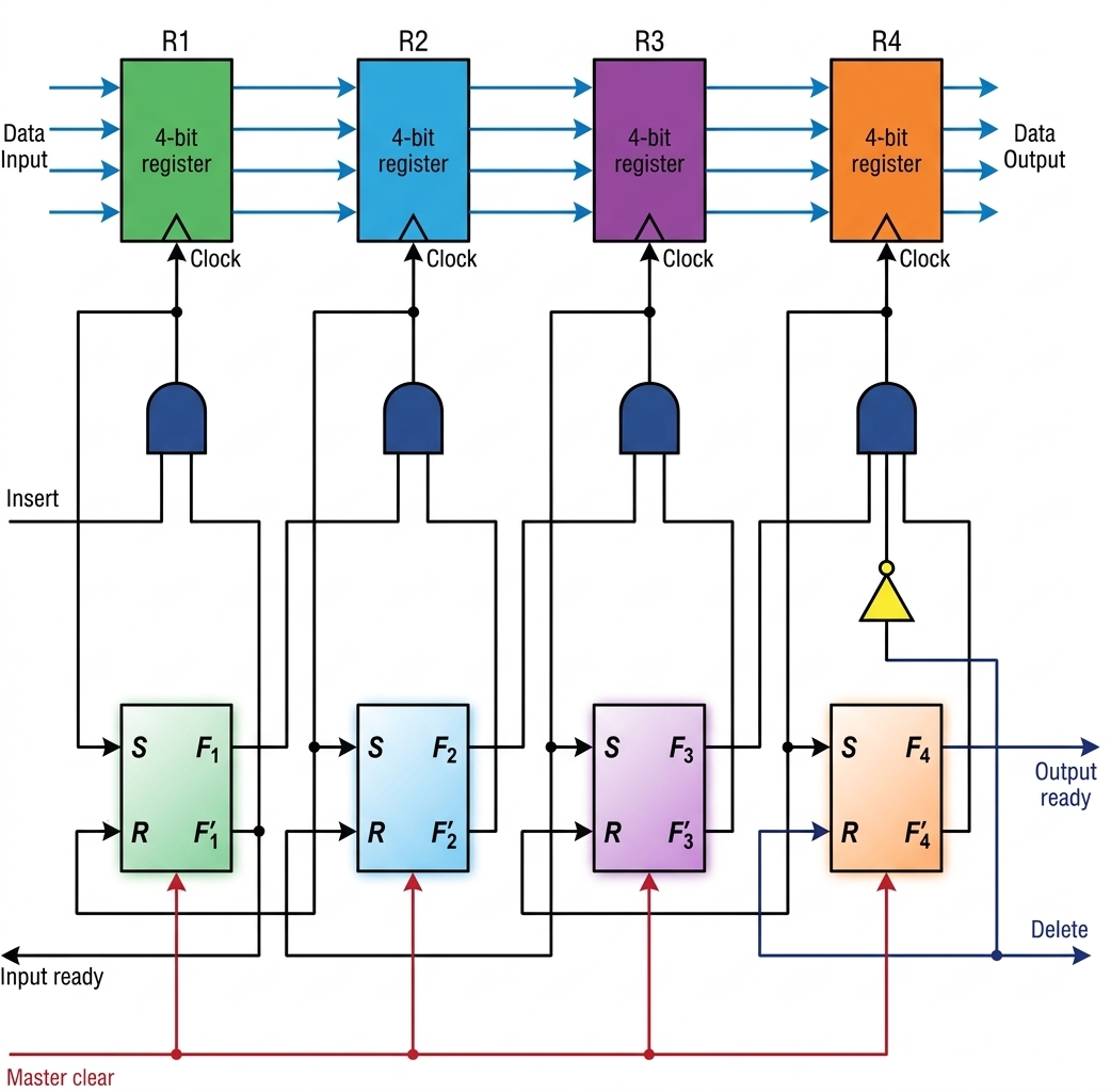
  • Managed by interlocked control flip-flops and handshaking signals (Insert/Delete) that automatically shift data to the next available register stage.
  • Enables asynchronous input/output operations
FIFO Buffer Structure
Source Handshaking

Shows 4x4 FIFO memory structure using a falling-through control logic that enables asynchronous data transfer by shifting data through registers based on the status of individual stage flip-flops.

Structure & Indicators:

  • Capacity: The circuit stores four words (4 bits each). You can make it "wider" by adding bits to registers or "deeper" by adding more registers.
  • Status Flags (Fi): Each register has a corresponding control flip-flop (F).
    1. F = 1: The register is full (contains valid data).
    2. F = 0: The register is empty (invalid data).

Ripple-Through:

  • Automatic Shifting: Data automatically moves to the right if the current register is full (Fi = 1) and the next one is empty (Fi+1 = 0).
  • The Transfer: When this "Full-to-Empty" condition is met, a clock pulse is generated that:
    1. Copies data from Ri to Ri+1.
    2. Sets Fi+1 to 1 (marking it full).
    3. Resets Fi to 0 (marking it empty).
  • Data keeps "falling" toward the output until it hits a register that is already full or reaches the final stage (R4).

Input & Output Handshaking:

  • Input Ready: If R1 is empty (F1 = 0), the system signals it can accept data.
  • Insert: Triggering this line loads data into R1 and sets F1 = 1, which immediately tells the system the input is "busy" until the data ripples forward.
  • Output Ready: When F4 = 1, it signals the destination that valid data is waiting in R4.
  • Delete: When the destination accepts the data, it triggers "Delete." This resets F4 to 0, creating an empty slot that allows data in R3 to move forward.